

MPU6050 Gyroscope & Accelerometer Sensor Module (GY-521) – 6-Axis IMU with DMP for Arduino & Raspberry Pi
- Sensor IC: MPU6050 (also referred as GY-521)
- SKU:YTX25262014
- Sensing Axes: 6-Axis – 3-Axis Gyroscope + 3-Axis Accelerometer (MEMS)
- Supply Voltage (VCC): 3V – 5V DC
- Communication Interface: I2C (up to 400kHz Fast Mode)
- I2C Address: 0x68 (default) / 0x69 (AD0 HIGH) – Configurable
- ADC Resolution: 16-bit built-in ADC (high accuracy)
- Digital Motion Processor: Built-in DMP (offloads MCU processing)
- Temperature Sensor: Built-in onboard temperature sensor
- Auxiliary I2C: XDA / XCL pins for external sensor (e.g. magnetometer – 9-axis)
- Interrupt Pin: INT – FIFO buffer full indicator
- Output Type: Digital – I2C data frames (acceleration, gyro, temperature)
- Arduino Pins: SDA → A4, SCL → A5
- Compatibility: Arduino, ESP32, ESP8266, Raspberry Pi, STM32
Product Details
MPU6050 Gyroscope & Accelerometer Sensor Module (GY-521) – 6-Axis IMU with DMP
The MPU6050 Sensor Module (GY-521) is a high-performance, low-cost 6-axis Inertial Measurement Unit (IMU) that combines a MEMS 3-axis accelerometer and a MEMS 3-axis gyroscope on a single silicon die. Designed for low-power, high-accuracy motion sensing applications, it is widely used in drones, quadcopters, self-balancing robots, RC cars, unmanned vehicles, wearables, and gesture-controlled systems.
The onboard Digital Motion Processor (DMP) handles complex sensor fusion and motion processing algorithms internally — significantly reducing the computational load on the host microcontroller and improving overall system accuracy. An auxiliary I2C bus (XDA/XCL) allows connection to additional sensors such as a 3-axis magnetometer, enabling a complete 9-axis Motion Data output (acceleration + gyroscope + magnetic field).
Key Features
- Sensor IC: MPU6050 (InvenSense) — also known as GY-521
- 6-Axis Sensing: 3-axis gyroscope + 3-axis accelerometer on single die
- Built-in DMP: Digital Motion Processor for onboard sensor fusion and motion algorithms
- 16-bit ADC: High-resolution analog-to-digital conversion for precise readings
- I2C Interface: Up to 400kHz Fast Mode communication
- Configurable I2C Address: 0x68 (AD0 LOW, default) / 0x69 (AD0 HIGH)
- Built-in Temperature Sensor: Onboard ambient temperature measurement
- Auxiliary I2C Port: XDA/XCL for connecting external sensors (magnetometer, barometer)
- Interrupt Output (INT): Signals FIFO buffer full or data ready events
- Wide Voltage Range: 3V – 5V DC — compatible with 3.3V and 5V logic systems
- Low Power: Designed for wearable, smartphone and tablet applications
Technical Specifications
| Parameter | Specification |
|---|---|
| Sensor IC / Chip | MPU6050 (InvenSense) / GY-521 |
| SKU | YTX25262014 |
| Supply Voltage (VCC) | 3V – 5V DC |
| Communication Interface | I2C (up to 400kHz) |
| I2C Address | 0x68 (default) / 0x69 (AD0 HIGH) |
| Gyroscope Axes | 3-Axis (X, Y, Z) |
| Gyroscope Full-Scale Range | ±250 / ±500 / ±1000 / ±2000 °/s |
| Accelerometer Axes | 3-Axis (X, Y, Z) |
| Accelerometer Full-Scale Range | ±2g / ±4g / ±8g / ±16g |
| ADC Resolution | 16-bit |
| Digital Motion Processor | Yes (built-in DMP) |
| Temperature Sensor | Yes (built-in) |
| Auxiliary I2C | Yes (XDA / XCL pins) |
| Interrupt Pin | INT (FIFO full / data ready) |
| Output Type | Digital I2C data (acceleration, gyro, temperature) |
| Logic Level | 3.3V / 5V TTL compatible |
| PCB Dimensions | ~21 × 16 mm |
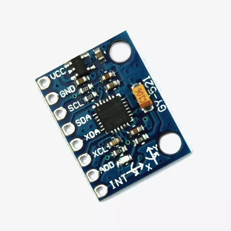
Pin Description
| Pin | Label | Description |
|---|---|---|
| 1 | VCC | Power Supply — Connect to 3.3V or 5V DC |
| 2 | GND | Ground — Connect to MCU GND |
| 3 | SCL | I2C Clock — Connect to A5 (Arduino Uno) / GPIO22 (ESP32) |
| 4 | SDA | I2C Data — Connect to A4 (Arduino Uno) / GPIO21 (ESP32) |
| 5 | XDA | Auxiliary I2C Data — for external sensor (e.g. magnetometer) |
| 6 | XCL | Auxiliary I2C Clock — for external sensor (e.g. magnetometer) |
| 7 | AD0 | I2C Address Select — LOW = 0x68 (default), HIGH = 0x69 |
| 8 | INT | Interrupt Output — signals FIFO full or new data ready |
Arduino Wiring (Uno)
| MPU6050 Pin | Arduino Uno Pin |
|---|---|
| VCC | 5V (or 3.3V) |
| GND | GND |
| SCL | A5 |
| SDA | A4 |
| AD0 | GND (for address 0x68) |
| INT | D2 (optional) |
| XDA / XCL | Not connected (unless using magnetometer) |
Supported Libraries
- Arduino IDE:
MPU6050by Electronic Cats / Jeff Rowberg - Arduino IDE:
Wire.h(built-in I2C library) - ESP32 / ESP8266: Same MPU6050 library via Arduino IDE
- Raspberry Pi (Python):
mpu6050-raspberrypilibrary - MicroPython:
mpu6050.pydriver
Arduino Sample Code
#include <Wire.h>
#include <MPU6050.h>

MPU6050 mpu;

void setup() {
  Serial.begin(9600);
  Wire.begin();
  mpu.initialize();
  Serial.println(mpu.testConnection() ? "MPU6050 connected" : "Connection failed");
}

void loop() {
  int16_t ax, ay, az, gx, gy, gz;
  mpu.getMotion6(&ax, &ay, &az, &gx, &gy, &gz);

  Serial.print("Accel: ");
  Serial.print(ax); Serial.print(", ");
  Serial.print(ay); Serial.print(", ");
  Serial.println(az);

  Serial.print("Gyro: ");
  Serial.print(gx); Serial.print(", ");
  Serial.print(gy); Serial.print(", ");
  Serial.println(gz);

  delay(500);
}
Compatible Platforms
- Arduino Uno, Nano, Mega, Leonardo, Pro Mini
- ESP8266 (NodeMCU, Wemos D1 Mini)
- ESP32 DevKit (3.3V logic — SDA: GPIO21, SCL: GPIO22)
- Raspberry Pi (all models — I2C bus)
- STM32, Teensy, MSP430, Nucleo boards
- MicroPython and CircuitPython boards
Applications
- Drones & Quadcopters: Flight stabilization and orientation control
- Self-Balancing Robots: Real-time tilt angle and angular velocity feedback
- RC Cars & Unmanned Vehicles: Motion sensing and directional control
- Gesture Recognition: Hand gesture-controlled systems
- Wearables: Step counting, activity recognition, posture monitoring
- Smartphones & Tablets: Screen rotation, motion gaming
- Vibration Analysis: Machine health monitoring
- Educational Robotics: IMU integration labs, STEM kits
Important Notes
- Connect AD0 to GND for default I2C address 0x68; connect to VCC for 0x69 (allows two MPU6050s on same bus).
- XDA and XCL pins only needed when connecting an auxiliary sensor like a magnetometer for full 9-axis output.
- The INT pin signals when the FIFO buffer is full — connect to an MCU interrupt pin for efficient data handling.
- Use 3.3V VCC when interfacing with ESP32 or other 3.3V logic boards.
- Allow 100ms warmup time after power-on before taking readings for stable output.
Additional Resources
Package Contents
- 1 × MPU6050 Gyroscope & Accelerometer Sensor Module (GY-521)
Note: This product is currently Out of Stock. Subscribe to restock notifications on the product page to be alerted when available.